Mitsubishi CIS Scanner
After successful installation and configuration of the scanner, it can be used directly as a camera.
Warning: Camera Link Configuration "TTL Encoder Driven" must be set for operationwith EasySightPro®.
Set up via live image
The camera settings are automatically set by the setup wizard and do not have to be inserted in the program management. The setup wizard is started via the "Live Image" button of the respective camera station.
For the initial setup it is recommended to follow the given steps in the menu sequence.
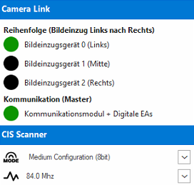
Menu "Connection"
Displays the connection status to the scanner and the basic configuration of the data output.
|
|
Camera Link | ||

|
Image grabber 0 (left) |
Indicates the connection status to Camera Link Card 1. This must be Green for proper operation. In the event of an error, check the configuration! |
|
|
|
Image grabber 1 (middle) |
||
|
|
Image grabber 2 (right) |
||
|
|
Communication Module + Digital IOs |
||
| CIS Scanner | |||

|
Output image format of the scanner |
Camera Link Output format of the scanner. (Default: Medium Configuration 8Bit) |
|

|
Image output frequency of the scanner |
The image output frequency determines the maximum speed of the scanner. The higher the speed, the more susceptible the transmission is to EMC interference. |
|
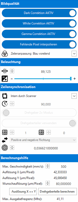
Menu "Basic settings"
Contain all settings relevant for image acquisition, such as exposure time, line synchronization and image compression algorithms.
|
|
Image quality | ||
|
Dark Correction |
Activates the factory black balance. (Recommended: ON) |
||
|
White Correction |
Activates the factory white balance. (Recommended: ON) |
||
|
Gamma Correction |
Activates the factory brightness correction. (Recommended ON) |
||
|
Interpolate missing pixels |
Adds the missing pixels for scanners with more than one module. The spaces are interpolated by the firmware. (Recommended: ON) |
||

|
Line adjustment |
Activates the color correction depending on the direction of movement of the scanner. This improves the image quality at color transitions. (Recommended: ON) |
|
| Illumination | |||

|
Exposure pulse length |
Length of the LED control in µs. The acquisition frequency (exposure time) of the scanner is fixed by the image output frequency. The image brightness is controlled by shortening the exposure pulse in relation to the acquisition frequency. |
|

|
Illumination divider |
Shortens the LED pulse by means of an internal divider. The lower the setting, the darker the image. |
|
| Line synchronisation | |||

|
Mode |
Operating mode with or without encoder. |
|

|
Line cycle |
For operation without encoder, the distance from line to line (in µs) can be set. |
|
|
Encoder mode |
Encoder edges: 2x or 4x |
||
|
Use encoder divider |
Using the encoder divider |
||

|
Encoder divider |
M + N Parameters for dividing the input frequency (see calculation tool) |
|

|
Acquisition direction |
Acquisition direction for encoder mode |
|

|
Encoder resolution |
Encoder resolution in mm per pulse |
|
| Calculation tool | |||
|
The calculation tool supports the determination of the correct encoder divider. |
|||
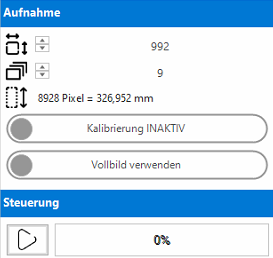
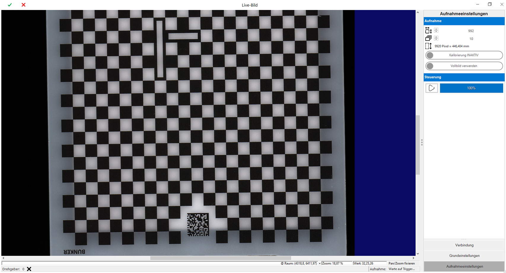
Menu "Acquisition settings"
The captured overall image in software automatically composed of smaller sub-images.
|
|
Acquisition | ||

|
Height of a partial image in pixels |
The frame size should be chosen so that the RAM and processor load is well distributed during the capture. (Recommended ~1000 Pixels) |
|

|
Number of partial images |
Each image acquisition consists of 2-50 partial images per module. |
|

|
Overall image height |
Height of the total image after all partial images have been acquired. For diagnostic purposes in pixels and millimeters. |
|
|
Calibration |
Activates the automatic calibration of the image using the acquisition parameters. The calibration is inserted as Sensor2D. |
||
|
Full image/region of interest |
This option allows you to cut out part of the image for inspection to save memory (ROI). |
||
| Control | |||

|
New image acquisition |
Triggers a new image acquisition. |
|